+91 99 49 444 123
Rock Anchoring.
Introduction:
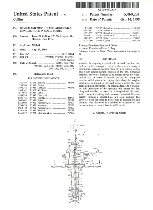
The Rock Anchoring & Foundation System is a Patented efficient and economical solution for the installation of Anchors and Foundations in Rock and/or any Solid Media. The System is Ecologically sound as it requires no excavation or removal of spoils and has no vibration, hammering or explosive requirements in its installation. No bonding agent required in the installation process as the System Components, upon their placement, directly transfers the applied design forces directly into the surrounding media. The System can be designed and installed to handle any intensity and type of loading placed upon it and is only limited by the strength of the surrounding media itself. It is easily installed with a minimum amount of time, labor and equipment. Once installed, the System can be easily tested to its design/ultimate load bearing capacity and is ready for immediate use with known installed structural integrity. No drying and/or curing time required.
The Rock Anchoring & Foundation System is a Patented efficient and economical solution for the installation of Anchors and Foundations in Rock and/or any Solid Media. The System is Ecologically sound as it requires no excavation or removal of spoils and has no vibration, hammering or explosive requirements in its installation. No bonding agent required in the installation process as the System Components, upon their placement, directly transfers the applied design forces directly into the surrounding media. The System can be designed and installed to handle any intensity and type of loading placed upon it and is only limited by the strength of the surrounding media itself. It is easily installed with a minimum amount of time, labor and equipment. Once installed, the System can be easily tested to its design/ultimate load bearing capacity and is ready for immediate use with known installed structural integrity. No drying and/or curing time required.
Anchor Design, Installation & Testing Procedures:
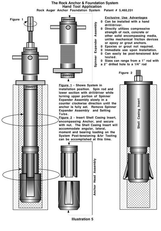
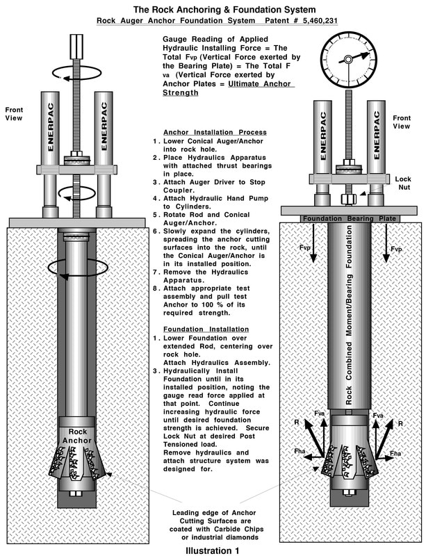
As with other rock anchors, the design of the System normally requires core sampling that identifies the consistency, type and strength of the load bearing media. The position/depth of the System is determined. The required design loading will determine the bar size required. Standard sizes available range from diameters of 1 to 2 1/2 inches with minimum ultimate strengths of 127.5 to 778 kips. The hole size required for the installation will normally be 1 inch greater than the bar diameter. Core sampling ideally would be taken at precise location the System is designed for. Upon withdrawing and inspecting the core samples, the Anchoring System can be installed immediately in the precise position as determined by the inspection of the samples. The System, consisting of the anchor head attached to the bar, which is encased by the spreading column, is lowered into the hole. The spreading/spinner apparatus is attached and centered in contact with the surface. The System is rotated, using the core sampling power unit, opening the anchor head into the load bearing media, in a predetermined controlled manner. This places the anchor head conically into the rock, which effectively utilizes the maximum strength of the load bearing rock via the Anchoring System. The casing, if used and required for coring by soils overburden, and/or the spreading column is removed, allowing the System to be immediately tested and placed into the use it was designed for.
Where the Rock Anchoring System is used in applications with rock at the surface, without coring requirements, its installation is greatly simplified. The drilled hole size is determined by the design loading. The hole is drilled to the desired System depth. The System, consisting of the anchor head attached to the bar, which is encased by the spreading column, is lowered into the hole. The spreading/spinner apparatus is attached and centered in contact with the surface. The System is rotated using the hole drilling power unit, opening the anchor head into the load bearing media, in a predetermined controlled manner. This places the anchor head conically into the rock, which effectively utilizes the maximum strength of the load bearing rock via the Anchoring System. The spreading column is removed allowing the System to be immediately tested and placed into its designed use. If required, the System may be post-tensioned in order to meet current seismic loading safety measures. Corrosion protection for the bars can be accomplished via any desired methods currently used. The force transmitting Anchor head can be made of stainless steel, which can handle any compressive force that is place on it. The bar is the only component of the System that experiences the tensile forces placed upon the System, which can also be made of stainless steel.
Foundation Design, Installation & Testing Procedures:
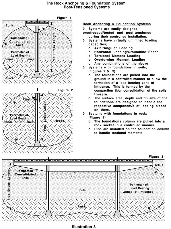
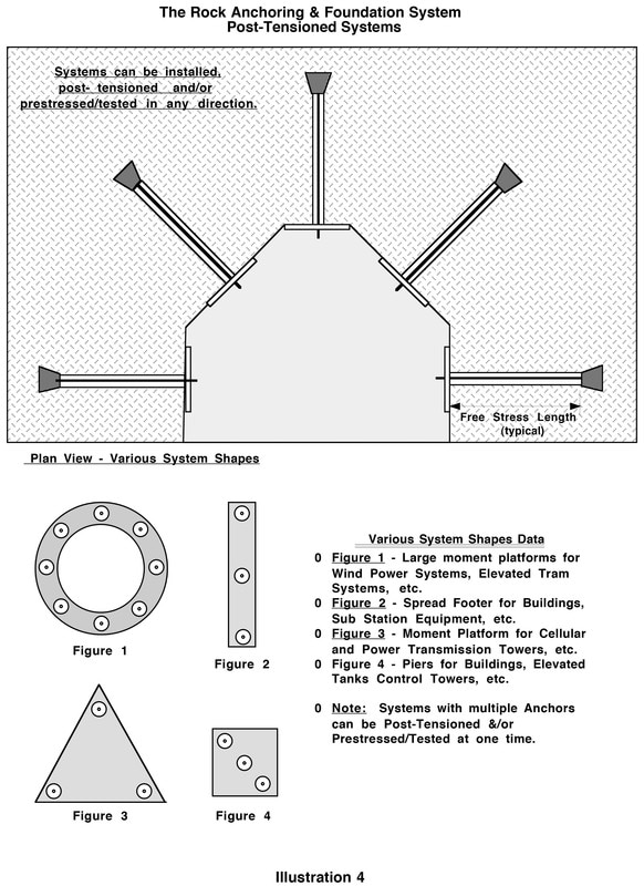
The Foundation System is installed using the Anchoring System, The Anchoring System provides a predetermined axial installing load in the precise direction required by the installation and loading of the Foundation System. Foundation uplift/pull out forces, when present in the System, are handled by directly attaching the Foundation to the Anchor in their final installed and tested position. The Foundation System can be designed, installed and tested to handle virtually and type and intensity of loading, such as overturning and torsional moments, angular and ground line shear and bearing. Upon reaching its final installed position, the final applied and held installing load is a direct indication of its ultimate strength, allowing the immediate use of the System. In rock the System can be pulled into a rock socket. When installed in soils the installing force is applied and installing movement is controlled in a predetermined manner. This increases the load handling capacities of the soils, via their compaction/consolidation, and Virtually eliminates settlement, as the entire Foundation System, including the load bearing soils, has been pre-stressed/tested to its design loading. Post-tensioned during the installation process. In the final installed position of the System any desired portion of the installing load may be locked in to meet current seismic loading safety measures. Corrosion protection for the Anchor bars and the Foundation System can be accomplished via any desired methods currently used. The force transmitting Anchor head can be made of stainless steel, which can handle any compressive force that is place on it. The bar is the only component of the System that experiences the tensile forces placed upon the System.
The Foundation System is installed using the Anchoring System, The Anchoring System provides a predetermined axial installing load in the precise direction required by the installation and loading of the Foundation System. Foundation uplift/pull out forces, when present in the System, are handled by directly attaching the Foundation to the Anchor in their final installed and tested position. The Foundation System can be designed, installed and tested to handle virtually and type and intensity of loading, such as overturning and torsional moments, angular and ground line shear and bearing. Upon reaching its final installed position, the final applied and held installing load is a direct indication of its ultimate strength, allowing the immediate use of the System. In rock the System can be pulled into a rock socket. When installed in soils the installing force is applied and installing movement is controlled in a predetermined manner. This increases the load handling capacities of the soils, via their compaction/consolidation, and Virtually eliminates settlement, as the entire Foundation System, including the load bearing soils, has been pre-stressed/tested to its design loading. Post-tensioned during the installation process. In the final installed position of the System any desired portion of the installing load may be locked in to meet current seismic loading safety measures. Corrosion protection for the Anchor bars and the Foundation System can be accomplished via any desired methods currently used. The force transmitting Anchor head can be made of stainless steel, which can handle any compressive force that is place on it. The bar is the only component of the System that experiences the tensile forces placed upon the System.
Present Art of Designing and Installing Rock Anchorages:
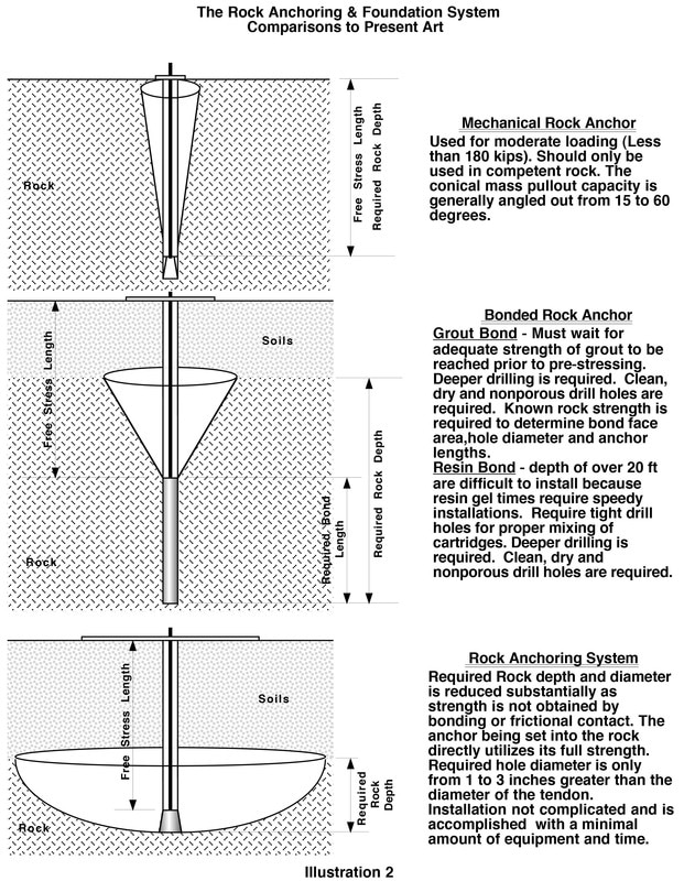
- High capacity rock anchors are generally post-tensioned. There are two distinct types of pre-stressed anchors in widespread use distinguished by tendon type: bar anchors and strand anchors. Both require drilling, cleaning and water testing of the borehole prior to establishing a cured grout bond of the tendon component to the rock bore hole surface. The bond zone, depth and diameter of drill hole surface required for bonding strength, will vary due to the types of rock encountered. The grout must be cured between the tendon component and the borehole wall prior to post-tensioning.
- Resin grout bonded rock anchors are currently considered as the most economical temporary rock anchor. Its installation requires a tight, non-permeable, clean and dry borehole. The bond length is limited, as its entire length must be pushed into the epoxy and spun prior to reaching the gel time of the epoxy, requiring fast installations. It cannot be used in all types of rock.
- Mechanical rock anchors are installed via an anchor shell and a cone used to develop a friction lock between the rock and head assembly. Their use is limited to concrete and soft rock and have minimal load-handling capabilities.
Present Art of Designing and Installing Combined Post-Tensioned Rock Anchorage and Foundation Systems:
There is no known practice system for installing foundations in rock, soils or any combinations thereof using rock anchors where the entire system, including the surrounding load-bearing media, can be tested and post-tensioned and/or load tested to a designed loading. Post-tensioning foundations would require a sound & reliable anchoring system for all rock and soils types with complete geotechnical site/media investigation prior to the system design. A combination of rock engineering and soils engineering experience would be required. In most cases foundations are designed with large safety factors, installed and placed into use without being post-tensioned and/or load tested.
There is no known practice system for installing foundations in rock, soils or any combinations thereof using rock anchors where the entire system, including the surrounding load-bearing media, can be tested and post-tensioned and/or load tested to a designed loading. Post-tensioning foundations would require a sound & reliable anchoring system for all rock and soils types with complete geotechnical site/media investigation prior to the system design. A combination of rock engineering and soils engineering experience would be required. In most cases foundations are designed with large safety factors, installed and placed into use without being post-tensioned and/or load tested.
Advantages of using The Rock Anchoring and Foundation System as compared to The Present Art of designing and installing rock anchors and foundations:
The proprietary apparatus and method for installing an anchor head conically into a rock socket is the enabling factor in the creation of the advantages and need for this technology as compared to existing practices. The Anchor Head directly transmits the applied load outwardly into the surrounding rock. This allows the full strength of the load bearing rock to be used. The following is a list of use advantages which is not all inclusive:
The proprietary apparatus and method for installing an anchor head conically into a rock socket is the enabling factor in the creation of the advantages and need for this technology as compared to existing practices. The Anchor Head directly transmits the applied load outwardly into the surrounding rock. This allows the full strength of the load bearing rock to be used. The following is a list of use advantages which is not all inclusive:
- Bonding grout or resins are not used.
- No curing or gel time is required.
- Drilling depth in rock is greatly reduced as required bonding length is totally eliminated.
- In a post-tensioned installation the entire rod, starting at the anchor head, can be considered as the tendon with the anchor head being the anchor.
- The pre-installation requirements of a tight, non-permeable, clean and dry borehole are totally eliminated.
- All installed Systems can be immediately placed into use upon completing the appropriate pre-designed installation process.
- The structural strength of the installed system is known upon installation, including posttensioned systems.
- The design process and its associated time requirements are greatly simplified along with the reduction of its associated liabilities:
- Provides a single system and method that can be used in the design & installation of standard or post-tensioned foundation and/or rock anchoring systems
- When the strength of the rock and, if present, the overlaying soils is known it is relatively simple to select the anchorage and design the foundation.
- There are no novel design procedures or formulae, required in the design process, that are not being used in the present art.
- Rock coring can be accomplished at the precise location of the installed system and the system can be immediately installed using the coring system. This would allow geotechnical testing firms to have an added revenue producing function
- Provides a large overall reduction in project costs in the following areas;
- Design time and costs.
- Elimination of required material and their associated installation and curing time.
- Rock drilling depths and borehole size are reduced significantly.
- Equipment costs are reduced
- Allows an advance in seismic engineering by providing an easily designed and installed posttensioned system for foundations and/or anchoring systems with known structural integrity upon their installation.
- Allows an improvement in permafrost engineering by providing an easily designed and installed post-tensioned system for foundations and/or anchoring systems with known structural integrity upon their installation.
- Allows development of a complete sound, safe and reliable system for mobile home foundations and anchors.
Barriers to Market Entry and their Possible Solutions:
- Acceptance of the technology −The only change is the rock anchor head which clearly apparent in its use and benefits.
- Lack of testing use/results − The only part of the System that is different is the anchor head and its installation. Testing can be easily & economically accomplished in surface rock along with being certified by a reputable geotechnical testing lab locally.
- Contractor acceptance, when different to materials and procedures they are currently using − Due to its time and cost benefits along with its known structural integrity, upon installation, designers and users will quickly change their requirements/specifications. Contractors will be able to perform the installations using the same equipment they have. The only added equipment needed would be the spinner/expanding apparatus, which could be purchased at a minimal cost.
- Lack of funding for development, testing and marketing – The simplicity and soundness of this proposal will attract investors, Another consideration would be to develop a strategic alliance with a rod and/or an anchor head manufacturer. The development of a hand tool system powered by a standard drill/driver for smaller anchors would open possible strategic alliances for marketing by major retailers and/or tool distributors for the home owner and small contractor markets, would also be a potential source of funding.
Use Areas/Industries:
Anywhere foundations and/or rock anchors are used is a potential use area. A marketing plan must be developed to target customers and/or alliances that would create sales in a manner that will satisfy our ongoing financial needs, which includes funding for the plan.
Anywhere foundations and/or rock anchors are used is a potential use area. A marketing plan must be developed to target customers and/or alliances that would create sales in a manner that will satisfy our ongoing financial needs, which includes funding for the plan.
|
|
|
|
|
|
Rock Anchor:
Rock Anchor is type of modern foundation system developed to install the anchors in Solid Rock or any Soil Media or combination of both. This system is an ecological sound system as it requires no excavation of soil, no removal of soil, no explosive material required during its installation of anchors in to rock. The Rock Anchoring System Components, upon their placement, directly transfers the applied design forces directly into the surrounding media of Rock. The System can be designed and installed to handle any intensity and type of loading placed upon it and is only limited by the strength of the surrounding media itself. It is easily installed with a minimum amount of time, labour and equipment. Once installed, the System can be easily tested to its design/ultimate load bearing capacity and is ready for immediate use with known installed structural integrity.
Rock Anchor is type of modern foundation system developed to install the anchors in Solid Rock or any Soil Media or combination of both. This system is an ecological sound system as it requires no excavation of soil, no removal of soil, no explosive material required during its installation of anchors in to rock. The Rock Anchoring System Components, upon their placement, directly transfers the applied design forces directly into the surrounding media of Rock. The System can be designed and installed to handle any intensity and type of loading placed upon it and is only limited by the strength of the surrounding media itself. It is easily installed with a minimum amount of time, labour and equipment. Once installed, the System can be easily tested to its design/ultimate load bearing capacity and is ready for immediate use with known installed structural integrity.
Anchor Design, Installation & Testing Procedures:
Pre checks before Design and Installation:
Pre checks before Design and Installation:
As with other rock anchors, the design of the System normally requires core sampling that identifies the consistency, type and strength of the load bearing capacity of soil media. The position/depth of the System is determined. The required design loading of the rock anchor system will determine the bar size required. Standard sizes available range from diameters of 25 mm to 60 mm with minimum ultimate strengths of 127.5 to 778 kips or 500 to 1000 N/mm2. The hole size required for the installation will normally be 25 mm greater than the bar diameter. Core sampling ideally would be taken at precise location the System is designed for installation of Rock Anchor. Upon withdrawing and inspecting the core samples, the permeability of the Soil and Soil Bearing Capacity, materials that the soil is made with are determined and the maximum loading capacity of the soil is determined. In addition to this test, the depth of the ground water table has to be calculated in order to determine the uplift pressure generated because of Water Table. The uplift pressure that is generated tries to lift the bar installed in to rock using Chemical grout which as a result will result in tensile load.
Design of diameter of bar and Embedment depth for Rock Anchoring:
After conducting test on the soil strata and determining its properties, necessary design is done by Geotechnical engineer in determining the Maximum Soil Bearing Capacity and the load that the soil/Rock strata can withstand.
The required design load for a constructing foundation should always be less than the load that the soil strata can withstand.
Required Load ≤ Load Soil Strata can withstand.
Calculation of Steel Failure of Rebar:
The steel failure of rebar has to be calculated and this steel failure should be always greater than the required design load for foundation. This steel failure determines the diameter of rebar required.
Required Design Load ≤Steel Failure.
Steel Failure
NRk,s = 0.87 X fy X Ast
fy = Nominal Yield Strength of rebar.
Ast = Area of Steel=πd2÷4
d = Diameter of Rebar.
To calculate the Embedment depth required:
The Embedment depth required to withstand the required design can be determined by the bond strength between the rebar installed and the soil strata. This mainly depends on the Bond strength of the Chemical grout used for fixing in the soil with rebar. The Ripple R Fix (Pure epoxy Resin based chemical) provides good bond strength to get the rebar fixed with the soil strata. The Embedment depth required for obtaining the design load is calculated according to the following formula.,
heff=N⁄π.d.τRK
N = Required Designed Load in kN.
heff = Embedment depth required in mm.
d = Diameter of rebar in mm.
τRK=Design Bond Strength of value in N/mm2.
The required design load distributed per square meter can be sufficed by the number of rebars grouted in the square meter with minimum axial spacing between two rebars.
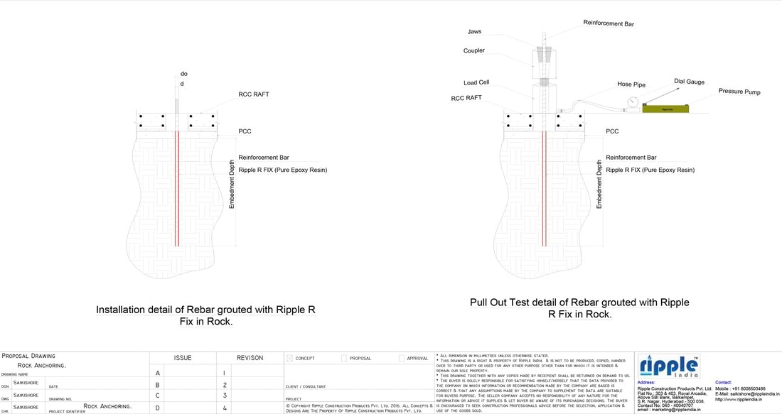
Installation Procedure with Ripple R Fix Chemical:
Testing Procedure for rebar installed in Rock anchoring:
- The installation procedure of rebar using Ripple R Fix Chemical has to be done after the design done according to the required load and checking the site conditions.
- The hole drilling process has to be decided between Rotary Hammer Drilling or Compressed Air Drilling on the basis of the embedment depth and the soil strata present at the location of Rock anchoring.
- The diameter of hole has to be taken with respective to the designed diameter of rebar. This can be achieved by adding 20 to 25 mm more designed diameter of rebar, Eg. If the rebar diameter is 32 mm, the diameter of the hole should be minimum 50 mm.
- The embedment depth can be drilled with the help of Rotary Hammer Drill machine if the embedment depth is less and the soil strata is loose to hard and the compresses air drilling machine is used to drill holes for deeper embedment depth and where the soil strata is hard.
- After achieving the desired embedment depth the hole is cleaned with compresses air if the hole is shallow and dry and a pressurised water flow can be used to clean the hole if the hole is deep and wet.
- Once the hole is cleaned properly, Ripple R Fix Chemical can be grouted into the hole by leaving first three trigger pulls outside filling the hole from the bottom by using dispenser gun.
- After filling the chemical to the 2/3rd of the hole, insert a cleaned rebar into the hole by rotating the rebar in clockwise direction.
- Align the rebar after inserting it into the hole and leave it for Curing time depending on the temperature of the base material.
- After curing the rebar(s) can be used for casting the foundation.
Testing Procedure for rebar installed in Rock anchoring:
- The rebar installed and cured with Ripple R Fix can be tested from Ripple India Technical Team.
- The site suitability to fix the equipment has to checked before conducting the testing.
- The development length (Projected length above the surface of ground) of the rebar should be minimum of 600 mm
- The maximum testing load that can be achieved with Ripple India tester is 600 kN for each rebar.
- Place the load cell in such a way that the rebar passes exactly from middle of the load cell.
- Fix the hose pipe to the load cell and to the Pressure pump.
- Fix the Dial Gauge to the pressure pump tightly such that there is no pressure leak.
- Close the pressure knob by rotating it in clockwise direction.
- Give pressure by pumping with the help of handle and observe the saddle protruding out of minimum of 10 mm.
- Place the coupler above the saddle and fix the jaws by hammering them between rebar and coupler such that there is no movement of coupler when tried to move with hand.
- Now give pressure by pumping with the handle such the saddle starts protruding out pushing the coupler system which holds the rebar in turn resulting pull out of rebar.
- Observe the reading on the dial gauge according to the load cell and record in the Field pull out test report of Ripple India.
- The design load has to be shown by the Ripple Team and the load beyond that might result in the failure of the rebar at its full capacity.